Nun muss ich auch was zum BLTOUCH am CR-10S schreiben, da ich mir das alles zusammensuchen musste. Ganz wichtig (IMHO): keinen Clone kaufen, sondern das Original!!! Mit dem Clone hatte ich einen formidablen Headcrash (kommt noch ein anderer Artikel zu).
a) Montage
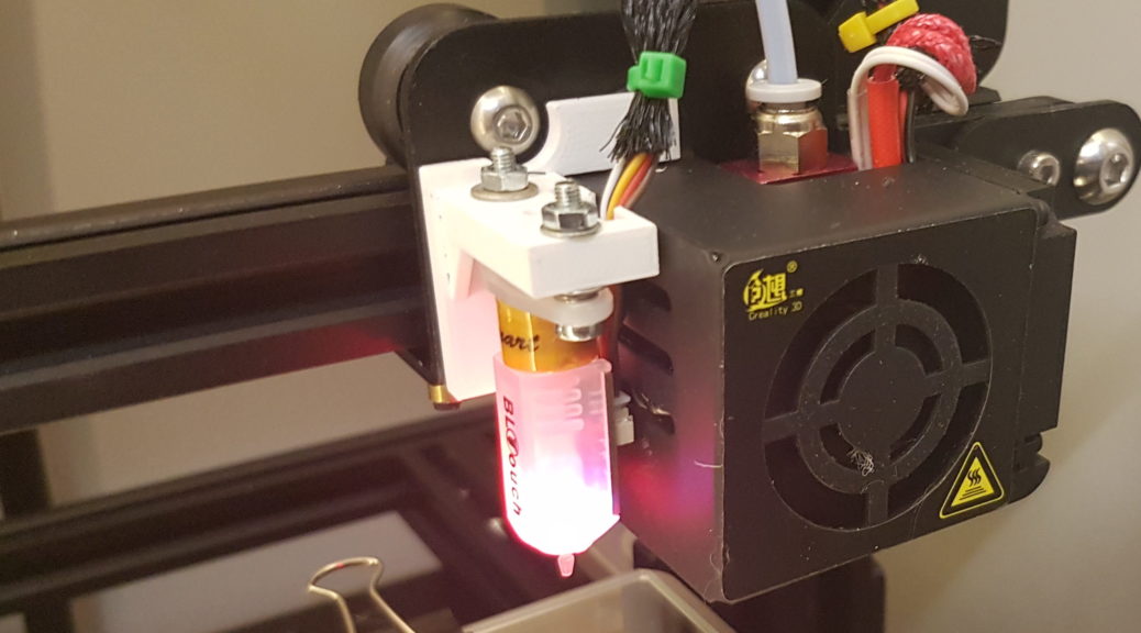
https://www.thingiverse.com/thing:2493610 ist der mount für den BL-Touch. Dafür braucht man etwas längere M3 Schrauben um das Teil am Kopf zu befestigen und ich würde statt der M2,5 Schrauben, die beim BL-Touch dabei sind, M3 Schrauben mit passenden Scheiben und Muttern nehmen.
Nun also erst den Mount montieren und dann die Schrauben von unten durch den BLTOUCH, die Federn dazwischen und das von oben mit den Muttern soweit hochdrehen, dass die Feder auf ca. 1-2 mm zusammengedrückt wird. Um das Ganze auf die richtige Höhe zu bringen, kann man sich noch die Lehre: https://www.thingiverse.com/thing:1538742 ausdrucken. der BLTOUCH smart sollte 8,5mm über dem Druckbett sein. Höher spricht er irgendwann nicht mehr an, tiefer kann der Stift am Druck hängen bleiben.
b) Firmwaresetup – mei, da hab ich jetzt keine Lust was zu schreiben. Halt ne aktuelle Marlin FW um die BLTOUCH Sachen erweitern.
b) Softwaresetup / Kalibrierung
- Heizen (Extruder und Bett auf Solltemperatur)
- Mal zur Sicherheit merken, was in M851 (Z-Offset) drinsteht
- EEPROM löschen mit M502 (oder nur M851 Z0 machen)
- EEPROM speichern mit M500
- mit G28 homen
- Z-Offset zur Sicherheit nochmal kontrollieren und evtl. löschen: M851
- Jetzt mach ich nochmal mit der CR-10 Controllerbox oder per Octoprint CR-10 Bed Levelling Plugin ein manuelles Levelling. Das ist nicht unbedingt nötig, hilft aber schon, die Einstellerei danach in Grenzen zu halten (ich hab somit -0.3mm Z-Offset hinbekommen)
- mit G28 homen
- G1 Z0 F60 (damit fährt der Extruder auf Druckhöhe)
- Nun ganz wichtig: Endstopp abschalten, wenn er denn an ist: M211 ist hier der passende Code: M211 S0 schaltet die Endstops aus.
- Nun mit G1 und absoluten werten im 0.1 mm Bereich oder dem Menü nach unten bewegen, bis ein doppelt gefaltetes Blatt leicht klemmt.
- Z Wert auf dem Display merken und mit M851 Z-1.0 (oder was halt rauskommt) speichern.
- M500 im EEPROM speichern
- Wenn man nun merkt, dass man weiter nach oben oder unten muss: Z wert entsprechend korrigieren.